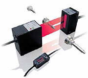
Oturum açın

Teknik zorluklar yaşamaktayız. Form gönderme işleminiz başarılı olmadı. Lütfen özürlerimizi kabul edin ve daha sonra tekrar deneyin. Detaylar: [details]

Download

Kaydol

Teknik zorluklar yaşamaktayız. Form gönderme işleminiz başarılı olmadı. Lütfen özürlerimizi kabul edin ve daha sonra tekrar deneyin. Detaylar: [details]

Download

Omron'a kaydolduğunuz için teşekkür ederiz

Hesabınızı tamamlamanız için şu adrese bir e-posta gönderildi:

Web sitesine geri dönün

doğrudan erişim

Bilgilerinizi aşağıya girin ve bu sayfadaki içeriğe doğrudan erişin

Text error notification

Text error notification

Checkbox error notification

Checkbox error notification

Teknik zorluklar yaşamaktayız. Form gönderme işleminiz başarılı olmadı. Lütfen özürlerimizi kabul edin ve daha sonra tekrar deneyin. Detaylar: [details]

Download

Gösterdiğiniz ilgi için teşekkür ederiz

Artık şuna erişebileceksiniz: ZX-GT

Şu adrese bir onay e-postası gönderildi:

Sayfaya devam edin

Bu belgeyi indirmek için lütfen veya doğrudan erişim edinin

ZX-GT

ZX-GT

Akıllı Lazer Mikrometre - Tüm yüzeylerde hassas ve hızlı

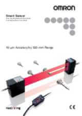
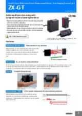
Yeni ZX-GT Akıllı lazer mikrometre Omron’un Akıllı Lazer Ölçüm platformunu tamamlamaktadır. ZX-GT kenarları algılayabilir, nesnelerin çaplarını ölçebilir ve her tür malzeme üzerinde pozisyonu hassas şekilde hesaplayabilir. CCD teknolojisine dayalı ZX-GT zor ortam şartlarında bile yüksek hassasiyet ve hız sağlar. Şeffaf nesneler, yansıtıcı yüzeyler veya farklı pozisyonlar sonucu etkilemez. PC Smart Monitor yazılımı, lazer mikrometrenin kurulumunu ve yapılandırmasını basitleştirir.

  • Yüksek hassasiyet: 5 – 10µm
  • Tüm yüzeyler
  • Uzun algılama mesafesi: < 500 mm
  • 28 mm'ye kadar çizgi genişliği
  • Çoklu kafalar için hesaplama ünitesi

Özellikler ve sipariş bilgisi

Ordering information

Sensors

Type

Optical system

Measuring width

Sensing distance

Resolution

Output type

Order code

Separate type

Through-beam

28 mm

0 to 500 mm

10 µm

NPN

ZX-GT28S11

PNP

ZX-GT28S41

Integrated type

40 mm

NPN

ZX-GT2840S11

PNP

ZX-GT2840S41

Controller

Power supply

Output type

Order code

DC

NPN

ZX-GTC11

PNP

ZX-GTC41

Accessories (order separately)

Set of interface unit and setup software PCs

Output type

Order code

NPN

ZX-GIF11A

PNP

ZX-GIF41A

Interface unit(RS-232C/binary output)

Power supply

Output type

Order code

DC

NPN

ZX-GIF11

PNP

ZX-GIF41

Setup software PCs

Name

Order code

Smart monitor GT

ZX-GSW11

Calculating units


Order code

Calculating unit

ZX-CAL2

Receiver-controller extension cable

Cable length

Quantity

Order code

Standard cable

Flexible cable

1 m

1 m

ZX-XGC1A

ZX-XGC1R

2 m

ZX-XGC2A

ZX-XGC2R

5 m

ZX-XGC5A

ZX-XGC5R

8 m

ZX-XGC8A

ZX-XGC8R

20 m

ZX-XGC20A

ZX-XGC20R


Specifications

Sensor

Item

ZX-GT28S11

ZX-GT2840S11

ZX-GT28S41

ZX-GT2840S41

Output type

NPN

PNP

Appearance

Separate type

Integrated type

Separate type

Integrated type

Light source

Visible semiconductor laser diode (wavelength 650 nm, CLASS 1 of EN60825-1/IEC60825-1, CLASS of FDA(21CFR 1040.10 and 1040.11)

Measuring width

28 mm

Sensing distance

0 to 500 mm

40 mm

0 to 500 mm

40 mm

Minimum sensing object

0.5 mm dia.1

0.2 mm dia.

0.5 mm dia.1

0.2 mm dia.

Linearity

±0.1% F.S.2

Resolution

10 µm (number of process values to average: 16)3

Temperature characteristic

±0.01% F.S/C4

Indicators (emitter)

Laser ON indicator (green), laser alarm indicator (red)

Indicator (receiver)

Optical axis setting indicator (green)

Laser OFF input/sync input

ON: Short-circuited with 0 V or 1.5 V max.
OFF: Open (leakage current: 0.1 mA max.)

ON: Short-circuited with power supply voltage or
power supply voltage -1.5 V max.
OFF: Open (leakage current: 0.1 mA max.)

Laser deterioration alarm output

NPN open-collector output
30 VDC 20 mA max.
Residual voltage 1.2 V max.

PNP open-collector output
30 VDC 20 mA max.
Residual voltage 2 V max.

Power consumption (emitter)

30 mA max.

Power supply voltage (emitter)

24 VDC+10%, -15% ripple (p-p) 10% max.

Dielectric strength

1,000 VAC, 50/60 Hz for 1 min

Insulation resistance

20 M Ω (at 500 VDC megger)

Operating ambient illumination
(emitter)

3,000 lx (incandescent light)

Operating ambient illumination
(receiver)

1,000 lx (incandescent light)5

Ambient temperature

Operating: 0 to 40°C, storage: -15 to 50°C (with no icing or condensation)

Ambient humidity

Operating and storage: 35% to 85% (with no condensation)

Vibration resistance (durability)

10 to 150 Hz single-amplitude: 0.75 mm for 80 min each in X, Y and Z directions

Degree of protection

IEC60529 IP40

Cable length

2 m

Material

Case: aluminum die-cast, Lens: glass

Weight (packed state)

Approx. 550 g

Approx. 570 g

Approx. 550 g

Approx. 570 g

Accessories

Laser warning labels, instruction sheet

F.S.: 28 mm measuring range of receiver

Controller

Item

ZX-GTC11

ZX-GTC41

Output type

NPN

PNP

Measurement cycle6

1.5 ms (standard mode (NORM))
0.5 ms (high-speed mode (FAST))7

Samples to average

1/2/4/8/16/32/64/128/256/512/1024/2048/4096

Analog output8

For current output: 4 to 20 mA/F.S., max. load resistance 300 Ω
For voltage output: ±4 V, (±5 V, 1 to 5 V9), output impedance 100 Ω

Timing input, bank switching input, zero reset input, reset input

ON: short-circuited with 0 V or 1.5 V max.
OFF: Open (leakage current: 0.1 mA max.)

ON: short-circuited with power supply voltage or
power supply voltage -1.5 V max.
OFF: Open (leakage current: 0.1 mA max.)

HIGH/PASS/LOW
Judgment output10
Sync output11

NPN open-collector output
30 VDC 50 mA max.
Residual voltage 1.2 V max.

PNP open-collector output
30 VDC 50 mA max.
Residual voltage 2 V max.

Indicator

Judgment output indicator: HIGH (orange), PASS (green), LOW (orange)
Main display (red) sub-display (yellow) bank 1/2 (orange), zero reset (green)

Main functions

Number of registered
setups

2 banks

Measurement mode

Interrupted beam width measurement, incident beam width measurement, outer diameter measurement, center position measurement, IC lead pitch,
IC lead width judgment, specified edge measurement, wire position measurement, glass edge position measurement

Display during
measurement

Measured value, resolution, threshold, voltage output value, current output value (number of display digits can be changed)

Zero reset functions

Offset setting of zero reset value, zero reset value memory

Hold

Sample hold, peak hold, bottom hold, peak-to-peak hold, average hold, delay hold

Timer functions

ON-delay, OFF-delay, one-shot

Adjustment functions

Optical axis adjust mode/light intensityt writing mode, variable binary level, variable edge filter, analog output scaling

Calculation

2 possible on up to two controllers (calculation Unit ZX-CAL2 is required for connecting controllers to each other.) A-B, A+B, width

Other

Measurement cycle setting, threshold setting, hysteresis setting, initialization, key lock

Temperature characteristic

±0.005% F.S./°C

Current consumption

150 mA max. (including receiver)

Power supply voltage

24 VDC+10%, -15% ripple (p-p) 10% max.

Dielectric strength

1,000 VAC, 50/60 Hz for min

Insulation resistance

20 M Ω (at 500 VDC megger)

Ambient temperature

Operating: 0 to 50°C, storage: -15 to 60°C (with no icing or condensation)

Ambient humidity

Operating and storage: 35% to 85% (with no condensation)

Vibration resistance(durability)

10 to 150 Hz single-amplitude: 0.35 mm for 80 min each in X, Y and Z directions

Degree of protection

IEC60529 IP20

Cable length

2 m

Material

Case: PBT (polybutylene terephthalate), cover: Polycarbonate

Weight (packed state)

Approx. 330 g

Accessories

Instruction sheet

Interface unit

Item

ZX-GIF11/-GIF11A

ZX-GIF41/-GIF41A

Compatible controller

ZX-GTC11

ZX-GTC41

Indicator

Power ON (green), controller communications (orange), controller communications error (red), RS-232C communications (orange),
RS-232C communications error (red), binary output (orange)

Communications port

RS-232C (9-pin D-sub connector)

12-bit binary output
(D11 toD0, GATE)

NPN open-collector output
30 VDC 20 mA max.
Residual voltage 1.2 V max.

PNP open-collector output
30 VDC 20 mA max.
Residual voltage 2 V max.

Power supply voltage

Supplied from controller (power consumption: 60 mA max.)

Dielectric strength

1,000 VAC, 50/60 Hz for 1 min

Insulation resistance

20 M Ω (at 500 VDC megger)

Ambient temperature

Operating: 0 to 50°C, storage: -15 to 60°C (with no icing or condensation)

Ambient humidity

Operating and storage: 35% to 85% (with no condensation)

Vibration resistance(durability)

10 to 150 Hz single-amplitude: 0.35 mm for 80 min each in X, Y and Z directions

Degree of protection

IEC60529 IP20

Cable length

RS-232C 0.5 m, binary output 2 m

Material

Case: PBT (polybutylene terephthalate), cover: Polycarbonate

Weight (packed state)

ZX-GIF_1A: Approx. 550 g
ZX-GIF_1: Approx. 330 g

Accessories

ZX-GIF_1A: Setup coftware (CD-ROM), 2 clamps, instruction sheet
ZX-GIF_1: 2 clamps, instruction sheet


1. Distance between emitter and receiver: 500 mm, measurement object at 250 mm from receiver. Glass ends of chamfer 0.1 mm or more can be detected in glass edge measurement mode. (at binary level 70%)

2. Linearity is given to be a typical error with respect to an ideal straight line when the distance between the emitter and receiver is 100 mm and light is blocked at a distance of 50 mm from the receiver. (On the ZX-GT2840_, the measurement object is measured at a distance of 20 mm from the receiver.)

3. The amount of fluctuation (±3 σ ) in the analog output when the distance between the emitter and receiver is 100 mm and a ZX-GTC_ is connected

4. Change in the light cutoff value on one side when the distance between the emitter and receiver is 100 mm and the light is half-cutoff at a distance of 50 mm from the receiver (On the
ZX-GT2840_, the measurement object is measured at a distance of 20 mm from the receiver.)

5. Standard mode (NORM) used

6. The first response time is “measurement cycle x (number of samples to average setting + 1) + 1 ms” max. For the second response time onwards, the specified measurement cycle time is output.

7. The response time in the high-speed mode (FAST) for the IC lead pitch and IC lead width judgment modes is 1 ms.

8. Current/voltage can be switched using the switch provided on the rear of the Controller.

9. Can be set by the analog output scaling function.

10. The error (ERR) state is displayed when all HIGH/PASS/LOW outputs turn OFF.

11. Normally, wire the sync output wire directly to the emitter's sync input wire and run the controller in the standard mode. On an NPN type controller, use an NPN type emitter, and on a PNP type controller, use a PNP type emitter. Wiring of the sync wires is not required when the controller is run in the high-speed mode.
(Note, however, that the controller becomes more susceptible to the influence of ambient light in this case.)

Size nasıl yardımcı olabiliriz?

Sorularınız veya fiyat teklifi almak için lütfen bizimle iletişime geçin ya da bir talep gönderin.

+90 (216) 556 51 30
Bizimle iletişime geçin

İletişime geçin ZX-GT

zx-gt prod

* ile işaretli bölümleri doldurmak zorunludur. Kişisel bilgileriniz gizli kalacaktır.

Text error notification

Text error notification

Text error notification

Text error notification

Text error notification

Text error notification

Country error notification

Text area error notification

Checkbox error notification

Checkbox error notification

Teşekkür ederiz. Talebiniz konusunda en kısa sürede bilgilendirileceksiniz.

Teknik zorluklar yaşamaktayız. Form gönderme işleminiz başarılı olmadı. Lütfen özürlerimizi kabul edin ve daha sonra tekrar deneyin. Detaylar: [details]

Download
+90 (216) 556 51 30
+90 (216) 556 51 30
Fiyat teklifi isteyin

Için teklif ZX-GT

Bu form ile seçtiğiniz ürün için bir teklif isteyebilirsiniz. * ile işaretli bölümleri doldurmak zorunludur. Kişisel bilgileriniz gizli kalacaktır.

zx-gt prod

Kişisel detaylar

ZX-GT

Text error notification

Text error notification

Text error notification

Text error notification

Text error notification

Text error notification

Country error notification

Teklif ayrıntıları

Select notification error

Select notification error

Text area error notification

Checkbox error notification

Checkbox error notification

Talebiniz için teşekkür ederiz. En kısa zamanda size bilgi verilecektir.

Teknik zorluklar yaşamaktayız. Form gönderme işleminiz başarılı olmadı. Lütfen özürlerimizi kabul edin ve daha sonra tekrar deneyin. Detaylar: [details]

Download
Fiyat teklifi isteyin

Dosya indirme